In Part I of this series, I covered the basics of copper cabling for voice and data. In Part II, I covered copper cable categories, certification and ratings. Now, it is time to talk about optical fiber or, as some people call it, “fiber optics”.
Pros and Cons
Optical fiber has been widely used for communications since the 1980s. Fiber has many advantages over copper cable. It is lighter, carries much more data over a single strand, further and with less susceptibility to noise. Fiber has its disadvantages, too. The cable itself is more expensive, although the cost differential is getting smaller all the time (especially with rising copper prices). Connectorizing the cable ends is more expensive and labor intensive. Also, the cost of the electronics at each end of the fiber (think Network Interface Cards (NICs) and switches) are significantly higher than the same devices for copper. Still, over the last 20 years especially, fiber has been replacing copper in core data and telecom networks. We see less of it in the “last 100 meters” between the telecom closet and the desktop, but this is slowly changing as well.
The Core of the Matter
Fiber cable is divided into two classes, single-mode and multi-mode. Single-mode fiber has a very small core of glass, allowing only a single ray of light to travel down the fiber. Because of the tiny size of this core, the precision (laser) electronics needed to inject and detect the ray of light are very expensive. Single mode fiber is typically used for long-haul (>1 km) outside plant applications
Multi-mode fiber, on the other hand has a much larger core. This allows multiple rays of light to travel down the fiber, resulting in multi-mode distortion. While the larger core allows for less demanding (cheaper, LED-based) electronics at each end, the distortion limits the bandwidth and distance capabilities of the fiber. Multi-mode fiber is typically used in short-haul / small campus or inside plant environments. I will focus on multi-mode fiber in the rest of this post.
Speed Limits
The oldest optical fiber cables you will find in your building might be multi-mode cables with a 62.5 µm core (1 µm “1 micron” = .001 mm) and a 125 µm cladding. By the early 2000s, it was more common to see multi-mode fibers with a 50 µm core and 125 µm cladding. These are typically referred to as 62 micron or 50 micron fibers, respectively. These older fibers would support ethernet speeds of 10 Mbps and 100 Mbps, but strained to reach 1 Gbps. Newer manufacturing technologies have allowed for more economical laser-optimized 50 µm multi-mode fibers capable of handling 10 Gbps ethernet. The electronics for this type of fiber typically use vertical-cavity surface-emitting lasers (VCSELs) instead of LEDs. While VCSELs are more expensive than LEDs, they are much less expensive than the lasers required for single mode fiber.
Optical Cable Construction
The optical fiber itself (core and cladding) can be manufactured using high quality silica glass or plastic. This fiber is then encased in a plastic sheath (sometimes called a jacket or outer cover).

OFNR and OFNP Sheaths
The materials used in the sheath determine the proper environment in which the cable can be used. If you recall, in Part II of this series we discussed CMR and CMP classifications for copper cables. These classifications determine whether the cable can be used in plenum return-air environments. An equivalent classification system exists for optical fibers. OFNP cables (Optical Fiber, Non-conductive, Plenum) are more fire-resistant and low-smoke and are suitable for plenum applications. OFNR cables (Optical Fiber, Non-conductive, Riser) are not. There are other classifications of fiber cables, but these two are the most common.
Staying On Budget
One of the key measurements of an optical fiber link is how much loss or attenuation of the signal occurs from end-to-end. There are several sources of loss in a link: the fiber itself, splices and connectors. When you plan a fiber link it is best to prepare a loss budget beforehand. The loss budget totals up the loss from fiber, splices and connectors. It is good to use both typical and worst-case numbers in your budget. This gives you an idea of how much loss you will have in the link. Then your equipment supplier can tell you if the equipment will work over that link. After the link is installed, you can compare the test results to your link budget to verify the quality of the installation.
Sorry For Your Loss
First of all, there is the intrinsic loss in the cable itself. You will see this specified in the data sheet for the fiber. They will usually quote fiber attenuation in dB/km (deciBels per kilometer) at a given wavelength. This may seem a little complicated; just make sure you are looking at the appropriate number for your application. Ask your equipment supplier what wavelength their equipment uses.
They may also spec a bandwidth-distance product for the cable which tells you how much data you can send over the fiber at what distance. A higher bandwidth product indicates a higher quality, lower attenuation cable.
Splice and Dice
There are also losses from splices along the link. If the cable is spliced, there will be a certain amount of loss associated with each splice. Since we are talking about multi-mode fiber, primarily in an inside plant application, we will ignore splicing for now.
Getting Connected
The last source of loss in a link is the connectors placed on the end of the fiber and the patch cords used to connect to the end equipment. If you think about it, this typically results in two pairs of connectors at each end of the fiber: the pair between the fiber end and the patch cord, and the pair between the patch cord and the equipment. Connector loss is specified in the data sheet for the connector. You can usually expect something less than 0.5dB per connector. There is a certain level of skill required to field terminate fiber without exceeding the loss specified in the connector data sheets. Think twice before attempting this yourself!
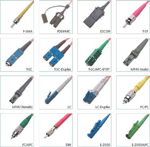
The last big choice when designing a fiber link is what connectors to use. If you are working into an environment with existing equipment, you may choose older legacy connectors like ST or SC. Consider the connectors on your equipment when choosing the appropriate connectors for your cable. The array of choices can seem overwhelming. Here are just a few of the options:
There are many more aspects to optical fiber cabling. I’ll have to save those for another time. My next post in this series (Part IV) will talk about structured cabling systems.
What are your experiences with optical fiber? Are you considering migrating parts of your cable plant to fiber? Share your thoughts in the comments.
Recent Comments